Thorp Air Command - T18.net
http://thorp18.com/thorpforum/

Panel Pictures
http://thorp18.com/thorpforum/viewtopic.php?f=30&t=6807
Page 1 of 2

Author:  Ryan Allen [ Wed Oct 05, 2011 2:26 pm ]
Post subject:  Panel Pictures

I am considering a new panel. Anyone out there care to post some pictures of their panel to give me some ideas to pick from?

Author:  Rich Brazell [ Wed Oct 05, 2011 3:52 pm ]
Post subject:  Panel Pictures

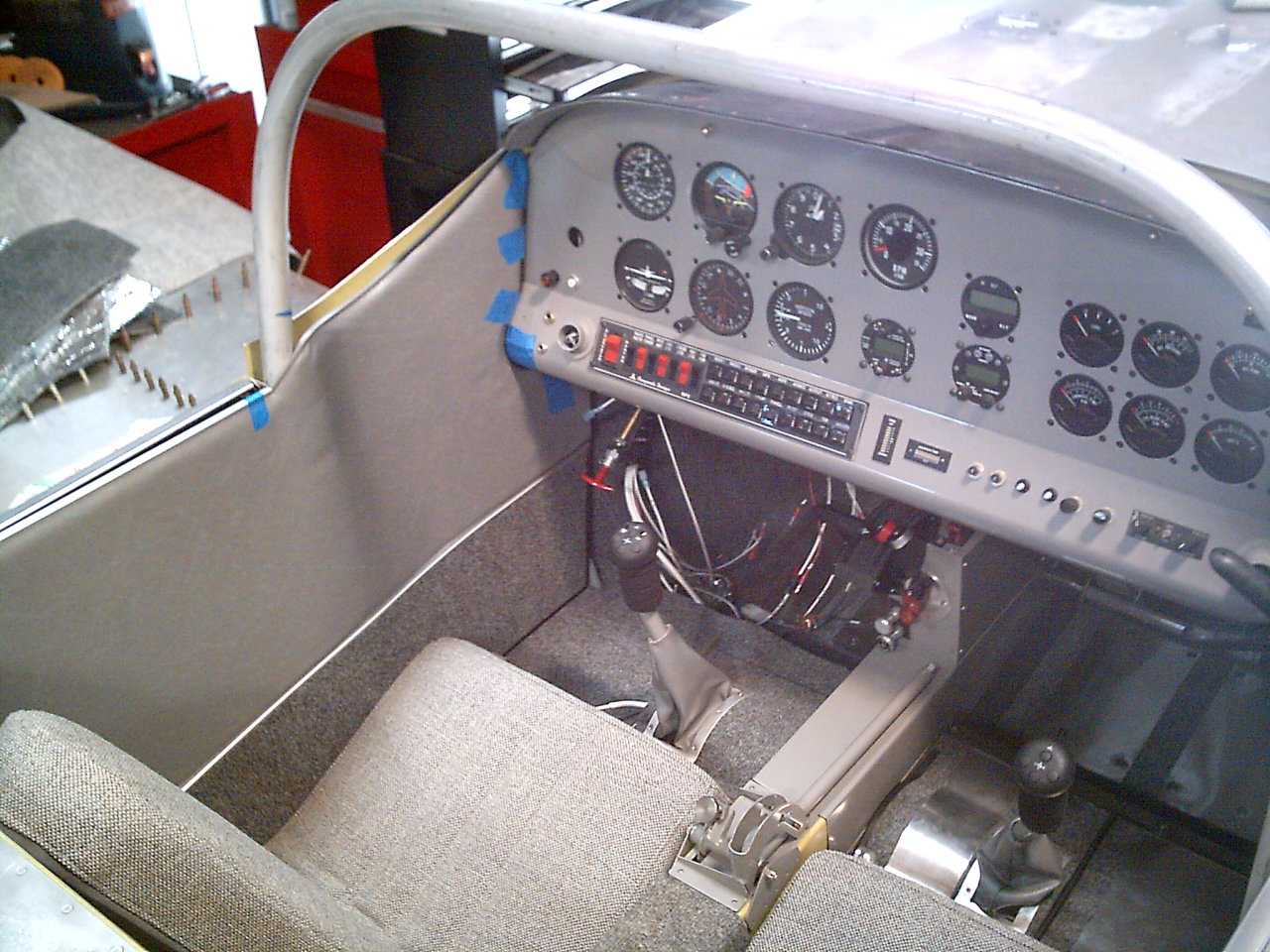
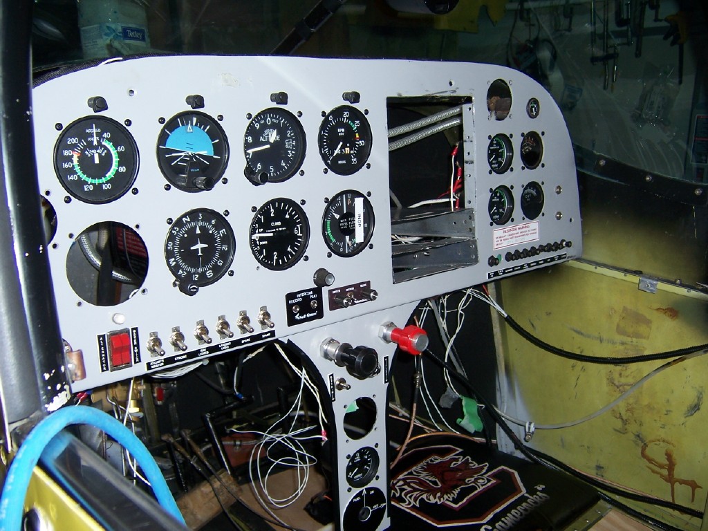
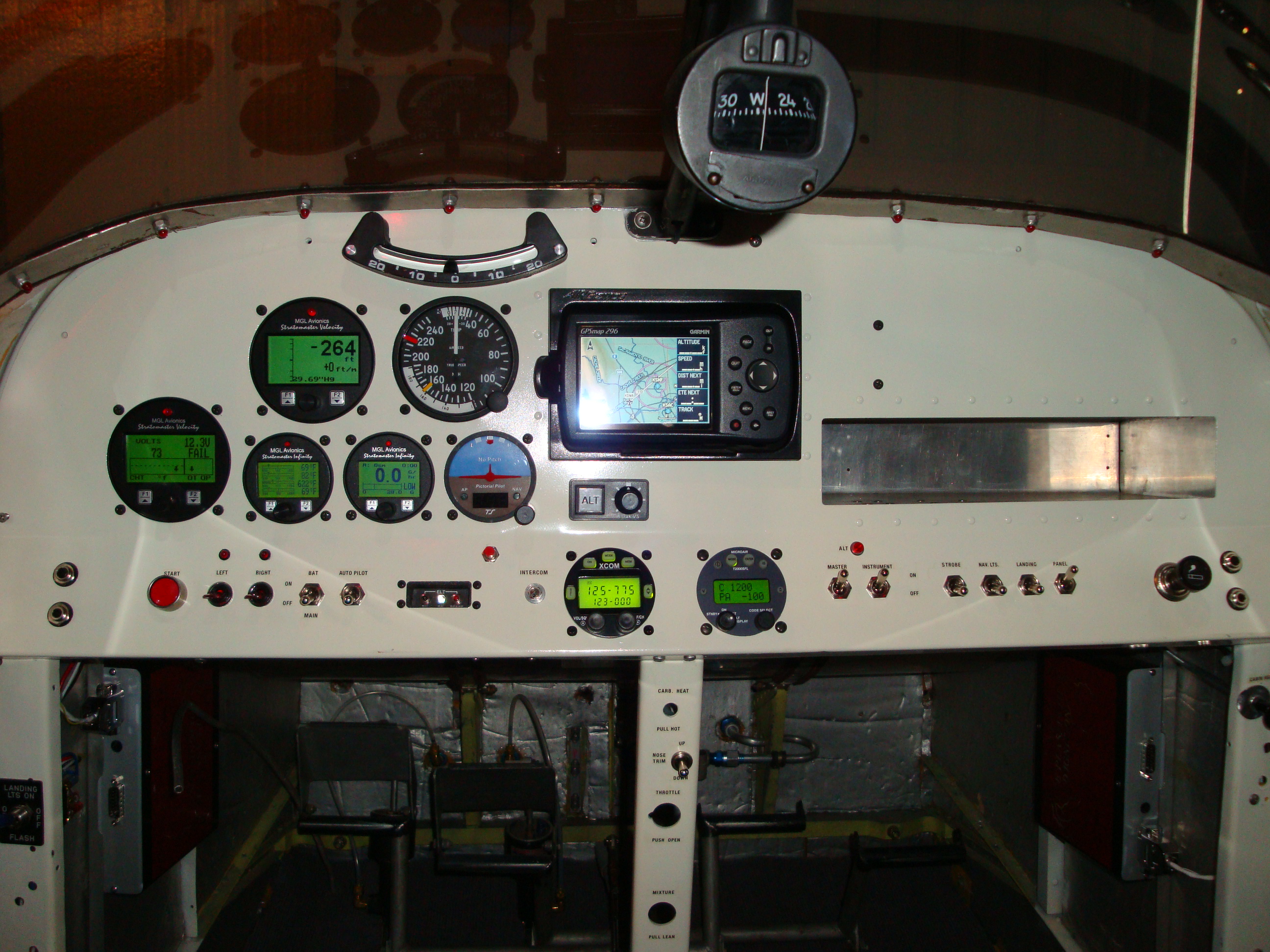
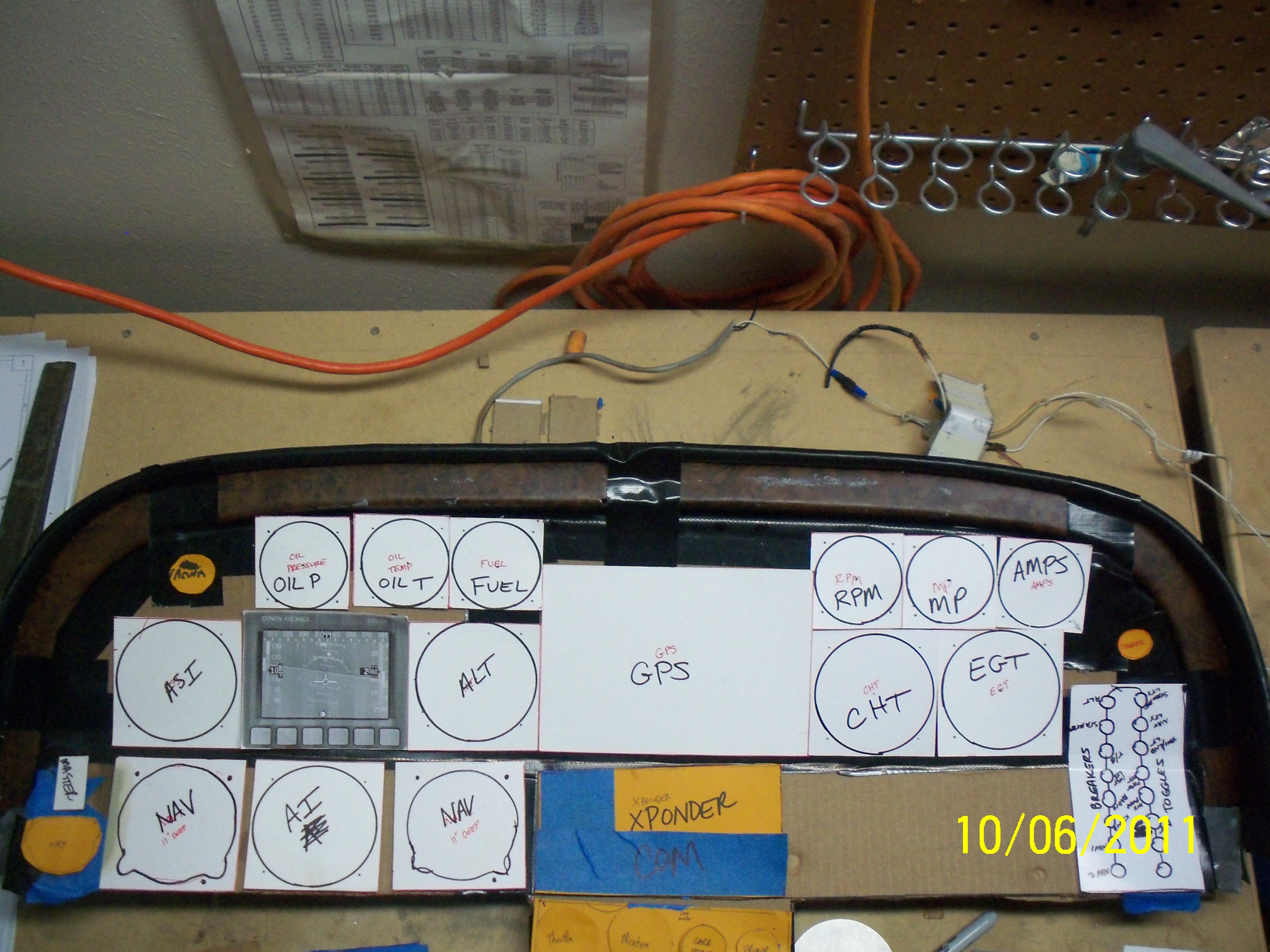
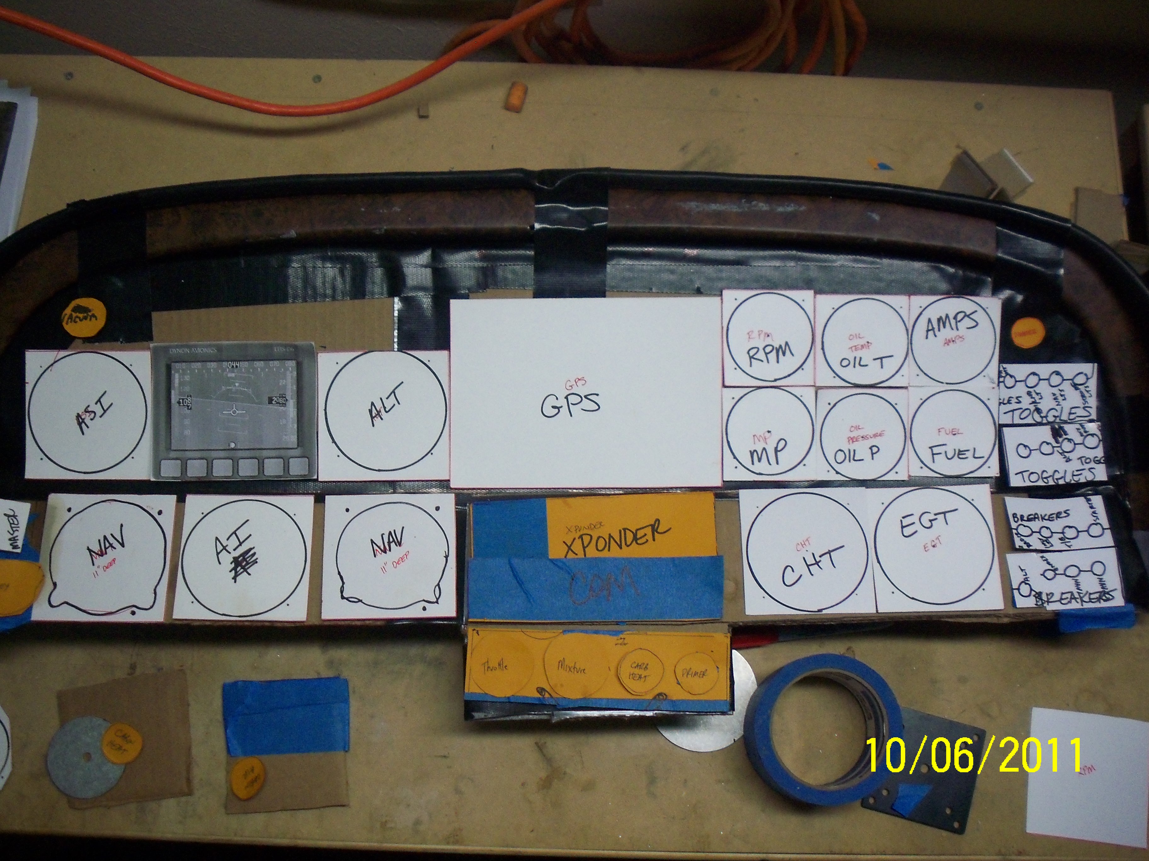
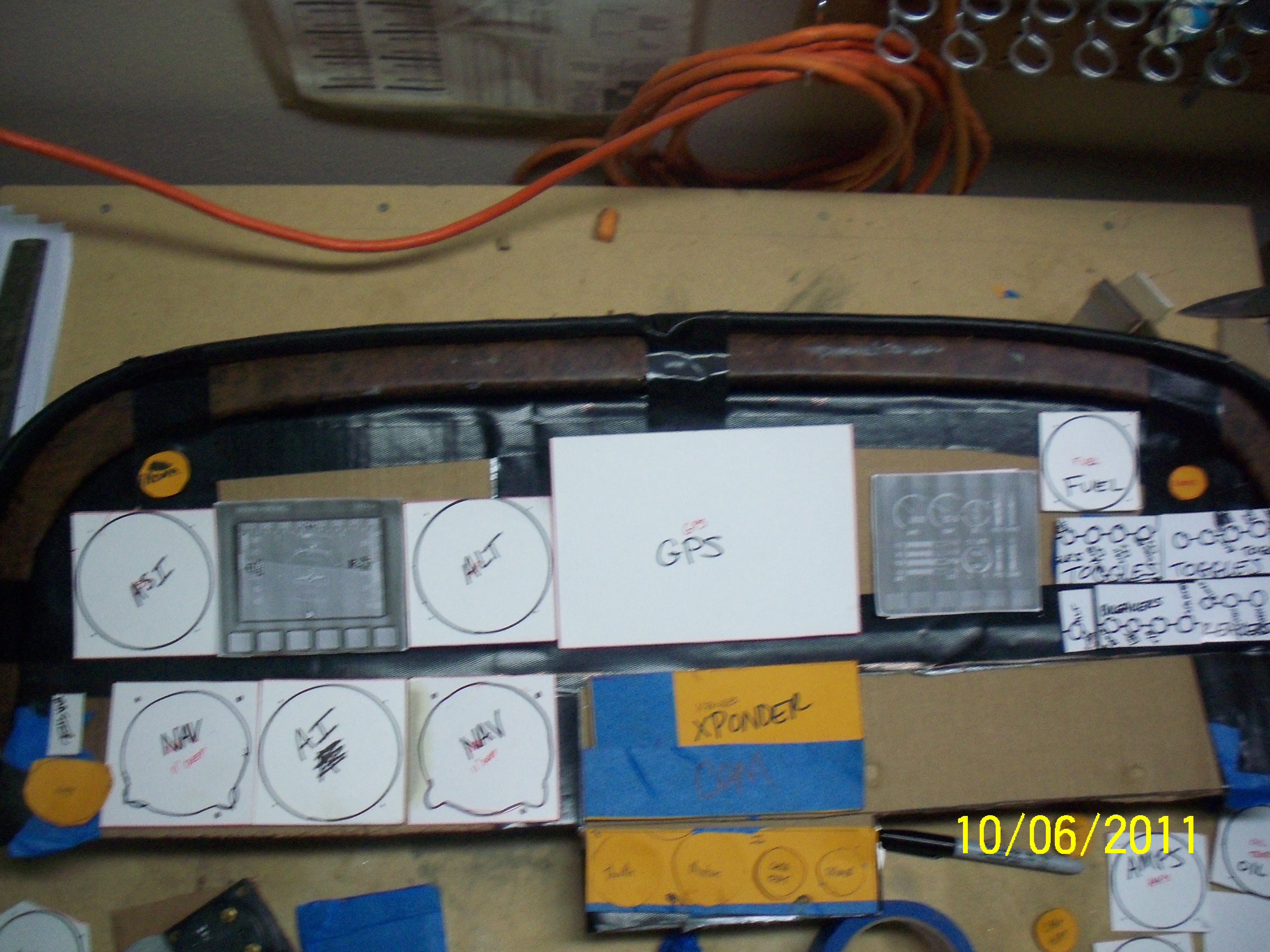
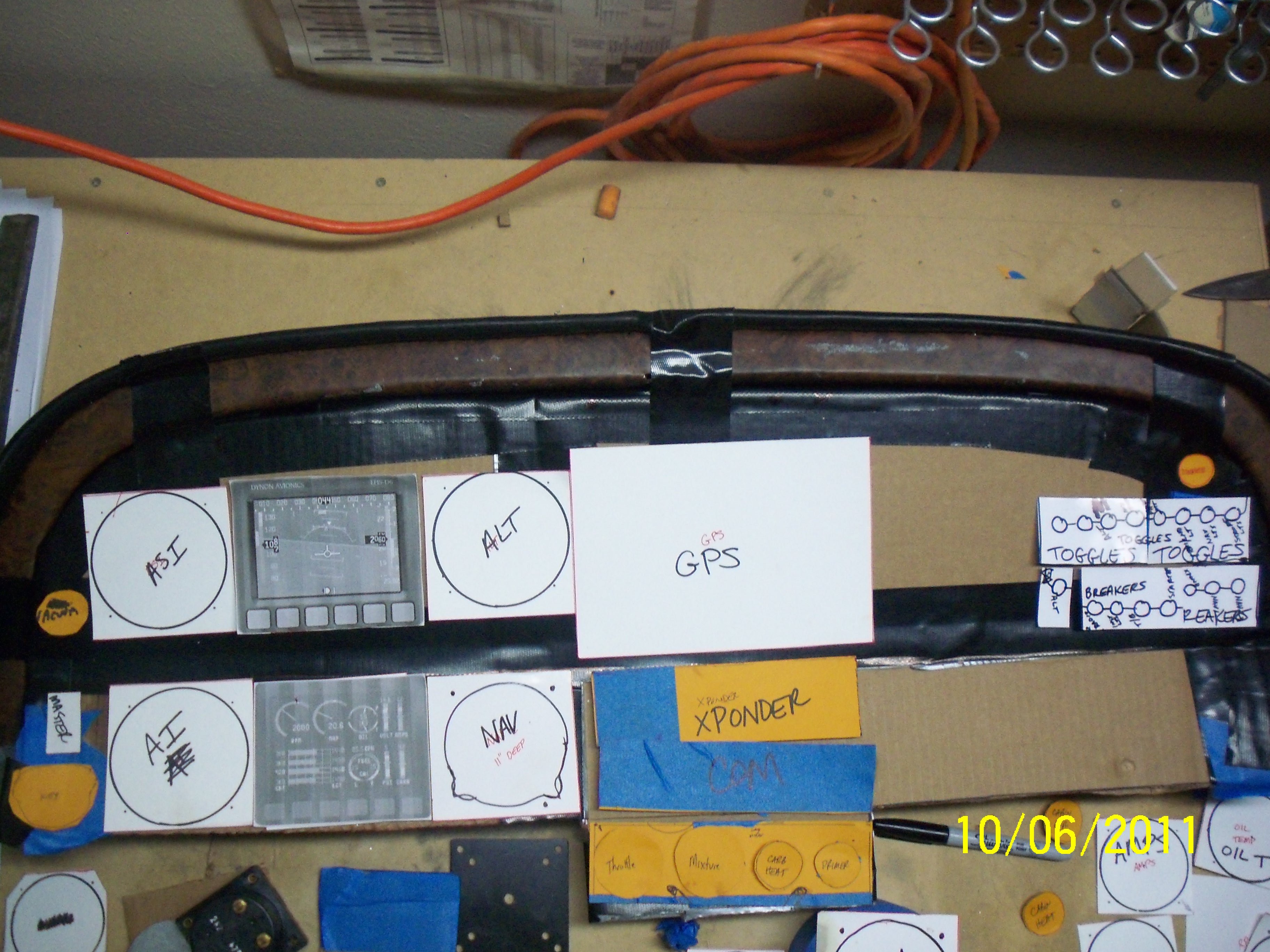
Ryan: One word of advice...PLAN ! Get a piece of poster board and lay out your instruments. I took my plans drawing for the instrument panel to Kinkos and made a copy. I spent several weeks laying out the instruments on the paper (full size) and trying to visualize their locations AND future locations for new instruments. Are they within easy reach (radios, etc). Future space for a GPS ? If you want to install an EFIS then space may not be a problem, but $$$ may be a limiting factor. I went with an all electrical panel to eliminate the vac. pump and all the monkey motion associated with that (reg./hoses/filter, etc). I used Westach gauges for my engine instruments and have been very happy with them.

At the VIS fly in I REALLY like Ira's mini UMA engine instrument gauges. You can pack a lot in a small space. The last thing I can add is do not start drilling holes in the panel w/o a little planning on the paper tiger (poster board) and sit in the aircraft with your poster board taped to the blank instrument panel to see how it "feels."

RB
NX115RX
Ser.# 2019

Image

Author:  Ryan Allen [ Thu Oct 06, 2011 3:30 am ]
Post subject:  Panel Pictures

I think you have a clean looking panel Rich. Yes, I would like to go glass but for now, its the old round gauges for me. I think I may put a little Dynon D6 in the panel but thats about it. I have done the cardboard thing and you're right its a great idea. I didnt really mean to get into a panel upgrade but my AI went out on me and before I knew it, I had the entire interior out. Im talking side panels, rudder cable covers, panel, seats, everything. I wanted to do it at some point, but I wasnt planning to do it right now. I figure while its down, I should go ahead and do it all.

Author:  Bill Williams [ Thu Oct 06, 2011 4:50 am ]
Post subject:  Panel Pictures

Consider the "six pack" layout for flight instruments. The rest is your preference. Also note Rich has a turnout at the bottom of the panel, this works good when installing radios, xponder, etc. without cutting into the gas tank. I hinged my panel for access to the back.

Author:  dickwolff [ Thu Oct 06, 2011 6:39 am ]
Post subject:  Panel Pictures

Image Insert:
Image


My airplane got an "extreme makeover" around 2004. One of the "improvements" this gentleman made was to build a sexy new panel. Nice job from the pilot's view, actually, but it appeared that he lost situational awareness of where the back of the instruments were with respect to the panel support structure on the backside. Fortunately this gentleman was quite resourceful and handy with the old tin snips. A hack here and a hack there... problem solved. No need to file and polish the edges... no one was going to see it. Cut wires? What are the chances?

Do keep in mind your three dimensional space. Everything is clear in hindsight... the better solution here would have been to put the switches and CB's at the top of the panel and move the instruments down.

Definitely go with as many 2.25 dia gauges as possible, and use as many multifunction gauges as possible. For example, Flight Data has a clock/g-meter/volt meter/OAT/timer/flight timer/ combo in a small light package for quite cheap. (GT-50). If I were independently wealthy, I wouldn't hesitate to put an EDM-700 in and to scrap the separate oil temp, cht, and egt gauges.

There's so much you can do when the slate is clean! And there is no end to what you can spend.

Yes - make the six pack STANDARD.

Author:  davem [ Thu Oct 06, 2011 2:10 pm ]
Post subject:  Panel Pictures

Here is the panel I have, which is a basic VFR only panel. The only steam gauge is the ASI. It has MGL instruments for Alt and VSI (including encoder for transponder); Fuel quantity and flow; Engine monitor, which shows CHT's and a 4 channel temp monitor which has the EGT's. A pictorial pilot autopilot is used, along with the Altitude hold (and adjust too). I don't tend to use the autopilot much, but I use the altitude hold all the time, including dialing in the ascents and descents. The only addition has been a stick on battery operated digital clock. The only thing I would do differently is paint the panel a medium or dark grey instead of the light color, as it reflects in the windscreeen whenever the sun is behind you.

I really like the location of the throttle and mixture controls on the narrow column. Carb heat, fuel shutoff and trim switch are also there. I have an excel file which show the panel layout (which is how I designed it) and the wiring diagram for the aircraft, but I cannot get the upload feature to work, so I can't attach it.

Image Insert:
Image

Put File Caption Here

Author:  Rich Brazell [ Thu Oct 06, 2011 2:37 pm ]
Post subject:  Panel Pictures

Speaking of painting...I powdered coating almost everything in the cockpit that was exposed metal (including the inst. panel, windshield frame and canopy frame). I find it holds up much better than any paint. Almost everything firewall foward that could be powder coated was also shot with the stuff. ( gear legs excluded, they were painted ). If you do "gouge" the stuff you can order a matching spray for touch ups. [;)]

RB

Author:  Ryan Allen [ Thu Oct 06, 2011 3:06 pm ]
Post subject:  Panel Pictures

Thats a good tip about the color gray and the reflection. I was gonna paint it gray. Heres what I have so far for the panel. What do you think....good, bad, ugly?

Image Insert:
Image

Panel

Author:  Rich Brazell [ Thu Oct 06, 2011 4:28 pm ]
Post subject:  Panel Pictures

Lower left. Looks like you are going to put the Dynon D6 (not sure about the P/N ?) I think that is a good choice considering the price of about $1600. As far as the engine inst. I would try to group them together a little more and like I said about Ira's 1 1/4" UMA engine instruments, if I had to do it over again I would go that route to save a lot panel space. I would also go vertical and stack mine like Ira did. I think Dan Eggleston did his that way. I set up mine for a "scan", going from the "six pack" on the left to the right for the engine inst.

Each panel is different as is each pilot. We have limited space on the panel, so what may work for you may not work for me.

RB

Author:  dickwolff [ Thu Oct 06, 2011 6:03 pm ]
Post subject:  Panel Pictures

I thought of something else. If I was starting over (which I may still do), I would put the breakers adjacent to the switches to reduce the length of wires that go back and forth. Mine add up to a fairly thick bundle.

Author:  Ryan Allen [ Thu Oct 06, 2011 6:29 pm ]
Post subject:  Panel Pictures

OK, I made some changes. I agree Rich, I thought it was a bit scattered myslef. I think #3 is the best looking below. What comments do yall have?

Image Insert:
Image

Option 1


Image Insert:
Image

Option 2


Image Insert:
Image

Option 3

Author:  Rich Brazell [ Thu Oct 06, 2011 8:15 pm ]
Post subject:  Panel Pictures

I think # 3 is the best...however, it appears you want the EFIS displays to be your primary instruments, therefore I would recommend put them in a line on the top row... EFIS ADI/GPS/ENG instruments Below the steam gauges ASI ( ADI right below your EFIS ADI)/ALT. The toggle switches I think are too far to the right and should be on the lower left side of the panel or lower middle at least. If you look at my panel, I used the Composite Design electrical panel. Comes pre-wired with switches and C/B's. It does make wiring a lot easier and the replacement parts are available at most electronic stores.

RB

Author:  fytrplt [ Fri Oct 07, 2011 3:32 am ]
Post subject:  Panel Pictures

I can't really tell, but putting the carb heat next to the mixture is a no-no. Carb heat goes to the left of the throttle. Make sure you round the corners of the engine control panel as it will be right at your knees when installed.

Author:  Rich Brazell [ Fri Oct 07, 2011 6:28 am ]
Post subject:  Panel Pictures

Good point about rounding the bottom edge of the panel. I took mine to a HVAC shop that had a HUGE press and he put the bottom bend in it and also rounded the bottom edge like it shows in the plans. Only thing I had to do was sand out the marks left by the die.

RB

Author:  Ryan Allen [ Fri Oct 07, 2011 5:51 pm ]
Post subject:  Panel Pictures

Im making some changes for you guys to peruse. I'll post a pic when I can. I appreciate the input thus far.

Page 1 of 2 All times are UTC - 6 hours [ DST ]
Powered by phpBB® Forum Software © phpBB Group
https://www.phpbb.com/