Thorp Air Command - T18.net

Supporting Owners, Builders and Pilots of the Thorp T-18 and its variants.
It is currently Sun Apr 28, 2024 11:14 pm

All times are UTC - 6 hours [ DST ]


Post new topic Reply to topic  [ 28 posts ]  Go to page Previous  1, 2
Author Message
Tim Brown
 Post subject: Smoke in the cockpit!
PostPosted: Tue Jul 26, 2011 1:04 pm 
Full Member
Full Member

Joined: Wed Oct 21, 2009 10:24 am
Posts: 135
Images: 0
First off....I wish to thank everyone that has been helping me with this, I really really really want to get this fixed so I can fly this summer :)

To answer...

The 30 amp breaker that popped when I had the "incident" was reset and has not popped again, as a matter of fact despite what the alternator shops tell me the alternator does not produce any current at all on the airplane.

The connections on the alternator are becoming more clear to my myopic eyes...there is the standard plastic push and lock plug on the side, I am told by Ace Auto Electric that one terminal (the one closest to the positive terminal (left one when viewed holding the alternator with the pulley facing forward) is power (+) for the field and the right terminal is for the alternator failure circuit (light).
There are two blue wires coming out the back of the thing that go to the alternator side of the master switch, the unit will not produce any power (on the test stand) unless these are connected together.
The last wire is simply a ground from the case of the alternator to the wire mesh shielding around the BIG (+) terminal that runs to the firewall.
I am a bit baffled by that wire since the alternator case is attached to the engine and the engine is well grounded to the airframe.
there is a photo of the back of the alternator in my album..
http://thorp18.com/forum/photo_album_vi ... 15&cid=640


Last edited by Tim Brown on Tue Jul 26, 2011 1:04 pm, edited 1 time in total.

Top
 Profile Personal album  
 
Victor Thompson
 Post subject: Smoke in the cockpit!
PostPosted: Tue Jul 26, 2011 4:34 pm 
Jr. Member
Jr. Member
User avatar

Joined: Mon Dec 21, 2009 11:02 pm
Posts: 51
Images: 12
Location: Merrickville, Ontario, Canada
Tim: I have been following your electrical problem and have reviewed the suggestions that the other (more electrically inclined than myself) have suggested, indicates an unserviceable alternator.

This despite the alternator shop(s) saying the alternator is good, when you put it on the aircraft it still produces no current or very low (170 millivolts) when you spin it up.

Without slaving in a known quality (serviceable alternator) which I am sure is expensive proposition, I am drawn back to basic electricity:

1. Broken or damaged wire, wire connections, installation.
2. Poor ground, corrosion, loose connection.

http://www.nflite.com/ChargingSystem.html

This article suggests some cheap potential fixes, master switch(alternator side) , circuit breaker and poor line connections in the charging systems. It also suggest that a lot of people replace alternators and other expensive components when it is poor wiring issue.

It has the schematics for a Cherokee and I understand that you have an alternator with a built in voltage regulator (so separate items may not be applicable) however it gives a component by component breakdown and a good troubleshooting ideas for you.

I might be inclined to swap out the master switch as you did have a smoke and short in this area and re-visit the charging system lines before investing in an alternator.

Again, best of luck.

_________________
Victor J Thompson
C-GIRQ
"In Memory Of Dad"


Last edited by admin on Tue Jul 26, 2011 4:34 pm, edited 1 time in total.

Top
 Profile Personal album  
 
Rich Brazell
 Post subject: Smoke in the cockpit!
PostPosted: Tue Jul 26, 2011 4:38 pm 
Hero Member
Hero Member

Joined: Wed Oct 21, 2009 12:33 pm
Posts: 3095
Images: 64
Location: Jamul, CA (San Diego area)
Tim: Going back to your original msg you say you pulled the comm/transponder and them put it back in and had the no charge situation (caution lite/steady discharge. Sure sounds like the field wire may have come loose and then you grabbed a handful of wire and then all the excitment began ! I am not Captain Electrode but when the wires fried on the back of the master switch are you sure the switch is still good ? At least the field portion of the switch. Then you say the electric shop sez the unit is like Hoover Dam and will lite up the neighborhood, but when in the airplane...nothing ? Is the alternator field gettin excited ? I know I am ! [:p]

Hey Vic...are you doing a Vulcan mind melt with me ?

Shouldn't there be a 5 amp breaker for the field ?

RB


Last edited by Rich Brazell on Tue Jul 26, 2011 4:38 pm, edited 1 time in total.

Top
 Profile Personal album  
 
Tim Brown
 Post subject: Smoke in the cockpit!
PostPosted: Tue Jul 26, 2011 5:00 pm 
Full Member
Full Member

Joined: Wed Oct 21, 2009 10:24 am
Posts: 135
Images: 0
I replaced the master switch so that's not an issue anymore...

still looking and thanks for the ideas... I will report back with what I find

edit;
I even by-passed the alt side of the master by hooking the field wires directly together....no go :(


Last edited by Tim Brown on Tue Jul 26, 2011 5:00 pm, edited 1 time in total.

Top
 Profile Personal album  
 
copterplt
 Post subject: Smoke in the cockpit!
PostPosted: Tue Jul 26, 2011 9:17 pm 
Newbie
Newbie

Joined: Tue Oct 27, 2009 12:38 am
Posts: 21
Location: USA
IF YOUR ALTERNATOR HAS AN INTERNAL REGULATOR THAN YOU WILL HAVE 4 WIRES. ONE LARGE ONE THAT GOES TO THE HOT SIDE OF THE STARTER SOLENOID. OF THE OTHER TWO, ONE IS THE SENSING WIRE THAT WILL ALSO GO TO A HOT WIRE SOURCE NOTE,NOT SWITCHED. THE OTHER WIRE WILL GO TO THE MASTER SWITCH THRU THE AMP LIGHT, THIS IS A SWITCHED 12 V POWER SOURCE. THE BLACK WIRE IN THE ALTERNATOR IS A SEPERATE GROUND FOR THE INTERNAL REGULATOR. IF ITS BEEN BENCH TESTED AND WORKED THAN MOST LIKELY ITS YOUR WIREING????? HOPE THIS HELPED. PAUL


Last edited by admin on Tue Jul 26, 2011 9:17 pm, edited 1 time in total.

Top
 Profile  
 
Richard H Woodcock
 Post subject: Smoke in the cockpit!
PostPosted: Wed Jul 27, 2011 5:47 am 
Newbie
Newbie

Joined: Mon Nov 23, 2009 11:09 am
Posts: 41
Location: USA
All,
I ASSUMED that his hookup was like mine, and others I've seen that have only three wires. The "fat" wire, and two that get connected together and through the "alt" switch to + batt. Sorry. . . and thanks.

I wrote that there should (theoretically) be a ground wire from the alternator case to the engine block. That's so that the mechanical connections are not relied on - but many use star washers on these connections with good results. The "mystery" shield ground is for noise suppression, and most say it should be connected at one end only - so it can't carry current. But, that's not your problem.

The only other thought I have that might (or might not) be helpful is that with many of the old Delco separate regulator circuits, the trouble indicator got positive at the panel, through the light bulb, to the alternator. If the bulb burned out, the alternator would not charge, and some replaced it with a resistor. I think with an internal regulator that would be the wire closest to the fat wire, the other would go to +batt. The "modified" blue wires are a mystery - probably to shut it down, as you suggested.

This may help, it has a "typical" circuit if you scroll down:
http://www.expeditionlandrover.info/Del ... ators.html

_________________
Rich Woodcock
N114RW - T18CW


Last edited by Richard H Woodcock on Wed Jul 27, 2011 5:47 am, edited 1 time in total.

Top
 Profile  
 
Tim Brown
 Post subject: Smoke in the cockpit!
PostPosted: Sun Aug 07, 2011 5:34 pm 
Full Member
Full Member

Joined: Wed Oct 21, 2009 10:24 am
Posts: 135
Images: 0
I crawled under the panel and had a hard look at the wiring. As it turns out the 30 amp breaker that popped when I had the "incident" is one of two 30 amp breakers in parallel; I didn't know since they aren't labeled (I'm fixing that ASAP). The actual connections are very hard to see from under the panel since I can't focus that close (just the wrong distance; if it was six inches further away it would be fine) and the two breakers are in the top row (three rows)... what I saw though was the female plug terminal on the breaker that had popped was "barely" on the terminal end. (I must have pulled it almost off when I was installing the transponder; the wiring is all very tight back there.
When I tried to push that terminal onto the breaker it wouldn't budge but a little more force "broke" it off, seems it has fused itself to the terminal... I assume because of the crappy connection.

anyway I removed the two 30 amp SANG MAO 250 VAC 30 A (part #A-0701) breakers and plan on either replacing both with new 30 AMP breakers or one 60 AMP like this...

http://www.aircraftspruce.ca/catalog/el ... 070amp.php

I think this is the problem.... :)

btw; anyone out there got a 60 amp breaker they want to part with? (the price at ACS is reasonable but the shipping is brutal)


Last edited by Tim Brown on Sun Aug 07, 2011 5:34 pm, edited 1 time in total.

Top
 Profile Personal album  
 
Richard H Woodcock
 Post subject: Smoke in the cockpit!
PostPosted: Fri Aug 12, 2011 6:15 am 
Newbie
Newbie

Joined: Mon Nov 23, 2009 11:09 am
Posts: 41
Location: USA
I would never put two breakers in parallel. There's no guarantee they will share the load equally.

_________________
Rich Woodcock
N114RW - T18CW


Last edited by admin on Fri Aug 12, 2011 6:15 am, edited 1 time in total.

Top
 Profile  
 
Tim Brown
 Post subject: Smoke in the cockpit!
PostPosted: Fri Aug 12, 2011 6:35 am 
Full Member
Full Member

Joined: Wed Oct 21, 2009 10:24 am
Posts: 135
Images: 0
----I would never put two breakers in parallel. There's no guarantee they will share the load equally.----

I think that is what happened, one popped and was burned, the other was burned but didn't pop.... I should have the new breaker today (I hope) and will get it installed asap.

Thanks


Last edited by Tim Brown on Fri Aug 12, 2011 6:35 am, edited 1 time in total.

Top
 Profile Personal album  
 
Tim Brown
 Post subject: Smoke in the cockpit!
PostPosted: Sat Aug 13, 2011 6:41 pm 
Full Member
Full Member

Joined: Wed Oct 21, 2009 10:24 am
Posts: 135
Images: 0
Well I spent the afternoon upside down under the panel and swapped out the two 30 amp breakers and replaced them with a single 60 amp (from ACS); unfortunately it made no difference at all; 0 output from the alternator.

I measured 12.6 volts at post #2 on my alternator

Image

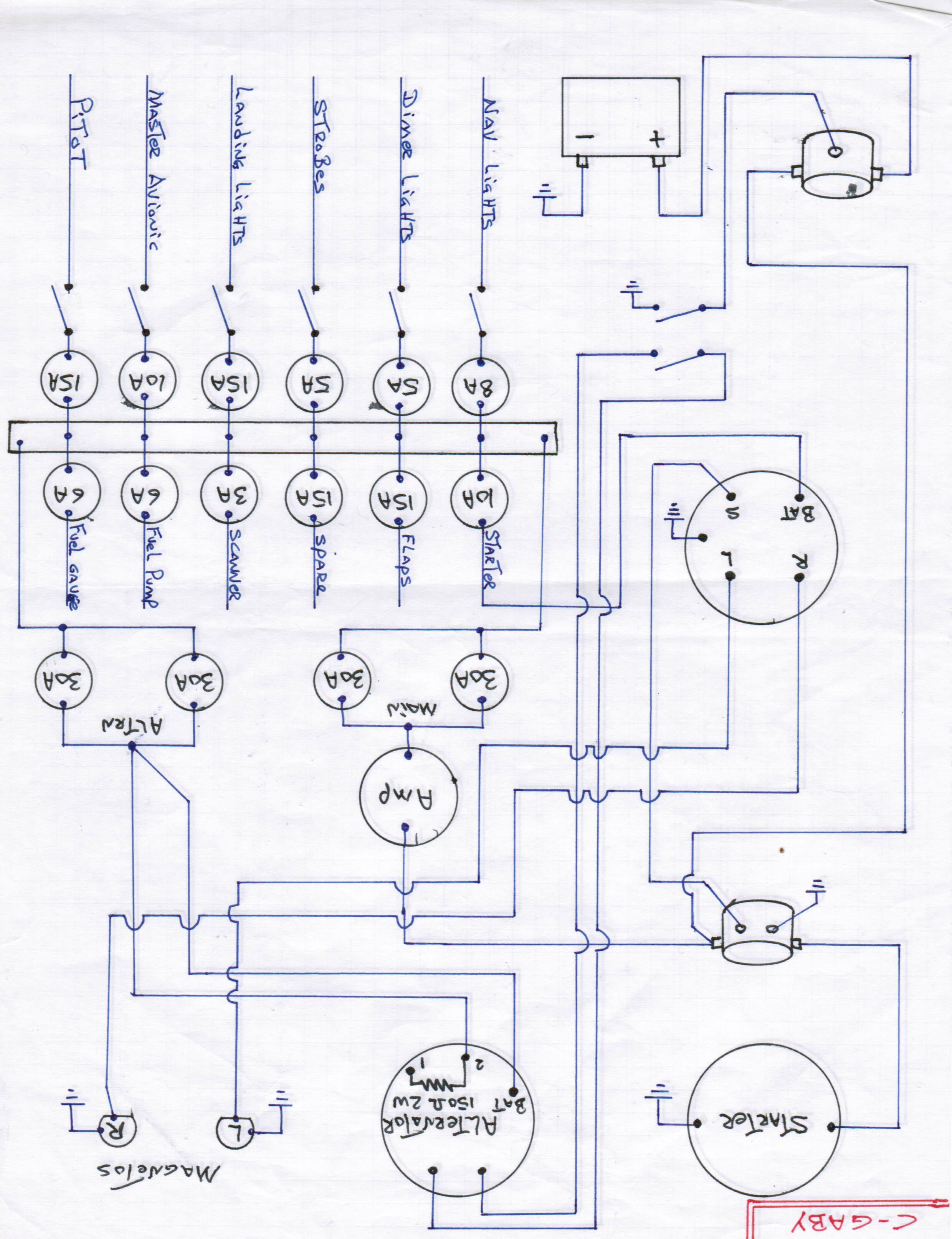
(there is another wiring diagram in my photo album if that helps)

with the master switch on (engine off), I also get 12.6 volts at post #1 (engine off). I studied the wiring diagram and am at a loss to explain why there is a resistor between post #1 and #2. None of the "experts" at the airfield knew what that was about either.

I disconnected the plug (GM wiring harness two plug white plastic connector) and measured 17 ohms between post #1 and #2.... that is contrary to what it APPEARS should be there (150 ohms)... is that the problem?....roasted resistor?

I am disheartened and just want this fixed...any ideas if I am on the right track.

ps;

"The only other thought I have that might (or might not) be helpful is that with many of the old Delco separate regulator circuits, the trouble indicator got positive at the panel, through the light bulb, to the alternator. If the bulb burned out, the alternator would not charge, and some replaced it with a resistor. I think with an internal regulator that would be the wire closest to the fat wire, the other would go to +batt. The "modified" blue wires are a mystery - probably to shut it down, as you suggested."

the alternator failed light works!


Last edited by Tim Brown on Sat Aug 13, 2011 6:41 pm, edited 1 time in total.

Top
 Profile Personal album  
 
leewwalton
 Post subject: Smoke in the cockpit!
PostPosted: Sat Aug 13, 2011 7:29 pm 
Administrator
Administrator
User avatar

Joined: Tue Oct 20, 2009 4:09 pm
Posts: 1705
Images: 107
Location: Houston, TX
Tim,
At this point I'd disconnect the alternator and run a jumper from the alternator to the 60 amp breaker, also run a jumper to the field terminal and see what you get. I'd be willing to bet things don't change much.

I had a similar situation a few years back, alternator shop swore up down mine was fine. Finally bit the bullet and swapped it out with a Nippondenso unit, all good since.

_________________
Lee Walton
Houston, TX
N51863,N118LW
KEFD


Last edited by admin on Sat Aug 13, 2011 7:29 pm, edited 1 time in total.

Top
 Profile Personal album  
 
lance38dt
 Post subject: Smoke in the cockpit!
PostPosted: Sat Aug 13, 2011 8:32 pm 
Full Member
Full Member

Joined: Thu Aug 05, 2010 3:22 pm
Posts: 143
Images: 0
Location: USA
Tim, I think you might have a couple shorted turns in the field windings, that would explain the resistance between pins one and two. Like Lee said bite the bullet.


lance38dt


Last edited by admin on Sat Aug 13, 2011 8:32 pm, edited 1 time in total.

Top
 Profile Personal album  
 
Rich Brazell
 Post subject: Smoke in the cockpit!
PostPosted: Sat Aug 13, 2011 8:42 pm 
Hero Member
Hero Member

Joined: Wed Oct 21, 2009 12:33 pm
Posts: 3095
Images: 64
Location: Jamul, CA (San Diego area)
I am not an electrican, but my basic understanding of the alternator means the field has to be excited before any juice is generated. I suspect the field. If I am wrong slap me around and send me to Washington !

RB


Last edited by admin on Sat Aug 13, 2011 8:42 pm, edited 1 time in total.

Top
 Profile Personal album  
 
Display posts from previous:  Sort by  
Post new topic Reply to topic  [ 28 posts ]  Go to page Previous  1, 2

All times are UTC - 6 hours [ DST ]


Who is online

Users browsing this forum: No registered users and 5 guests


You cannot post new topics in this forum
You cannot reply to topics in this forum
You cannot edit your posts in this forum
You cannot delete your posts in this forum
You cannot post attachments in this forum

Search for:
Jump to:  

[ Time : 0.162s | 13 Queries | GZIP : On ]